The esp8266 AT commands.
AT+RST // to reset the module.
AT+GMR // get the module version.
AT+UART_DEF=9600,8,0,1// set the uart speed.
AT+CWLAP // display all the routers around.
AT+CWJAP="SSID","PASSWORD" // connect to a specific router.
AT+CWQAP // disconnect from the router.
AT+CWSAP="SSID","PASSOWRD"// to make the module as access point.
AT+CWMODE=1 // normal wifi mode it's can connect to the router.
AT+CWMODE=2 // access point mode which you can connect to it.
AT+CWMODE=3 // working both modes at one time.
AT+CIPMUX=1 // make the module able to connect to the router and be an access point.
AT+CIFSR // display the IP address.
AT+CIPAP="192.168...." // make static IP to the module.
AT+CIPSERVER=1,80 //the page working on port 80.
AT+CIPSEND="ID","LETTERS NUMBER" //send data to the website.
AT+CIPCLOSE=0 // to shut down the page contact.
ESP8266-01Technical specifications
- 32-bit RISC CPU: Tensilica Xtensa LX106 running at 80 MHz **
- 64 KiB of instruction RAM, 96 KiB of data RAM
- External QSPI flash – 512 KiB to 4 MiB* (up to 16 MiB is supported)
- IEEE 802.11 b/g/n Wi-Fi
- Integrated TR switch, balun, LNA, power amplifier and matching network
- WEP or WPA/WPA2 authentication, or open networks
- 16 GPIO pins **
- SPI, I²C,
- I²S interfaces with DMA (sharing pins with GPIO)
- UART on dedicated pins, plus a transmit-only UART can be enabled on GPIO2
- 1 10-bit ADC
** CPU and flash clock speeds can be raised via overclocking on some devices and the 16 I/O are not available in all versions.
Tactically this all what you need for the UART communication and specifications of the module , the default baud rate of this module is 115200 bps.I use ESP-01 with Arduino for the digital pins, because this module have only two GPIO which it's shrinking my projects.
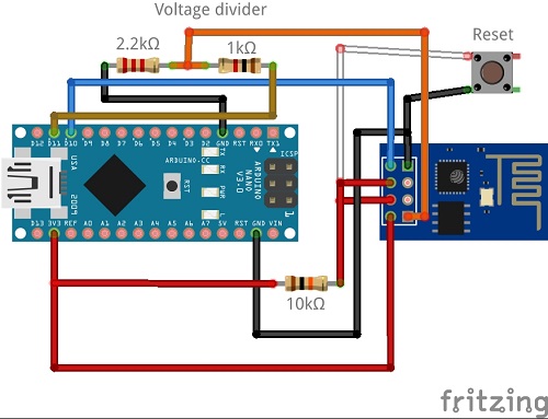
Demonstration
connect the VCC of the esp8266 to 3.3v and GND to ground, And CH_PD to 10k pull up resistorTX of the module connecting to RX of Arduino, RX of the module connecting to the Voltage divider then to TX of the Arduino.
Note:
this module working in the range 3.3V so any 5V signal it will de destroy it, only the Arduino pro mini because it'sworking with a 3.3V signal so, with this type of boards, you don't need a voltage divider.
We don't need to install any library.
simple serial communication
#include <SoftwareSerial.h>
String com;String ccc;
SoftwareSerial esp8266(10,11);

void setup() {
  // Open serial communications and wait for port to open:
  Serial.begin(9600);
  while (!Serial) {
    ; // wait for serial port to connect. Needed for native USB port only
  }

  Serial.println("Started");

  // set the data rate for the SoftwareSerial port
  esp8266.begin(9600);
  esp8266.write("AT\r\n");
}

void loop() {
  if (esp8266.available()) {
    com=esp8266.readString();
    Serial.println(com);
  }
  if (Serial.available()) {
    ccc=Serial.readString();
    esp8266.print(ccc);
  }
}
access point code
#include <SoftwareSerial.h>
#define D true
SoftwareSerial esp(10,11);
void setup()
{
  Serial.begin(9600);
  esp.begin(9600);
  //==================
  // start command
  sendweb("AT+RST\r\n",2000,D);
  sendweb("AT+CWMODE=2\r\n",1000,D);// This access point mode
  sendweb("AT+CWJAP=\"ssid\",\"password\"\r\n",10000,D);// put a name to the module and password
  sendweb("AT+CIFSR\r\n",1000,D);
  sendweb("AT+CIPMUX=1\r\n",1000,D);
  sendweb("AT+CIPSERVER=1,80\r\n",1000,D);
}
void loop()
{
  if (esp.available())
  {
    if(esp.find("+IP"))// when the client connect to the server
    {
      delay(1000);
      String web="<h1>HELLO WORLD</h1>";
      String cipsend="AT+CIPSEND=0,";
      cipsend+=web.length();
      cipsend+="\r\n";
      sendweb(cipsend,3000,D);
      sendweb(web,3000,D);
      sendweb("AT+CIPCLOSE=0\r\n",3000,D);
    }
  }
}
String sendweb(String comm,const int timeout,boolean de)
{
  String respons="";
  esp.print(comm);
  long time=millis();
  while((time+timeout)>millis())
    {
      while(esp.available())
        {
          char c=esp.read();
          respons+=c;
        }
    }
    if(de)
      {
        Serial.print(respons);
      }
      return respons;
}
Code to connect the router
#include <SoftwareSerial.h>
#define D true
SoftwareSerial esp(10,11);
//tx of esp gonig to pin 10
//rx of esp goning to pin 11
void setup()
{
  Serial.begin(9600);
  esp.begin(9600);
  //==================
  // start command
  sendweb("AT+RST\r\n",2000,D);
  sendweb("AT+CWMODE=1\r\n",1000,D);
  //==============================
  sendweb("AT+CWJAP=\"roter name\",\"router password\"\r\n",10000,D);
  sendweb("AT\r\n",1000,D);
  sendweb("AT+CIPMUX=1\r\n",1000,D);
  sendweb("AT+CIPSERVER=1,80\r\n",1000,D);
  sendweb("AT+CIFSR\r\n",2000,D);

}
void loop{}