Demonstration
Serial mode
connect the pins as the following- GND to grund
- VCC to +3.3 volt
- CS to grund
- SET to grund
- TX to RX of the FTDI breakout
- RX to TX of the FDTI breakout
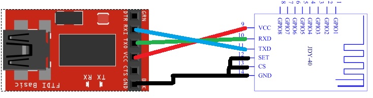
and then you have entered the serial mode, open the serial monitor and the speed of the baud rate to 9600 because it's the default serial communication speed of the module.
Setting Query:
1>. Baud rate:
| No. | Instruction | Response | Parameter |
| 1 | AT+BAUD<Param> | OK |
Param(1-7) 1:1200 2:2400 3:4800 4:9600 5:14400 6:19200 Default Value: 4 |
| 2 | AT+BAUD | +BAUD=<Param> |
2>. RFID
| No. | Instruction | Response | Parameter |
| 1 | AT+RFID<Param> | OK |
Param(0000-FFFF) Default Value:8899 |
| 2 | AT+RFID | +BAUD=<Param> |
3>. DVID
| No. | Instruction | Response | Parameter |
| 1 | AT+DVID<Param> | OK |
Param(0000-FFFF) Default Value:8899 |
| 2 | AT+DVID | +BAUD=<Param> |
4>. RFC
| No. | Instruction | Response | Parameter |
| 1 | AT+RFC<Param> | OK |
Param(001-128) Default Value:001 |
| 2 | AT+RFC | +RFC<Param> |
5>. POWE
| No. | Instruction | Response | Parameter |
| 1 | AT+POWE<Param> | OK |
Param(0-9) 0: -25db 1: -15db 2: -5db 3: 0db 4: +3db 5: +6db 6: +9db 7: +10db 8: +10db 9: +12db |
| 2 | AT+POWE | +POWE=<Param> |
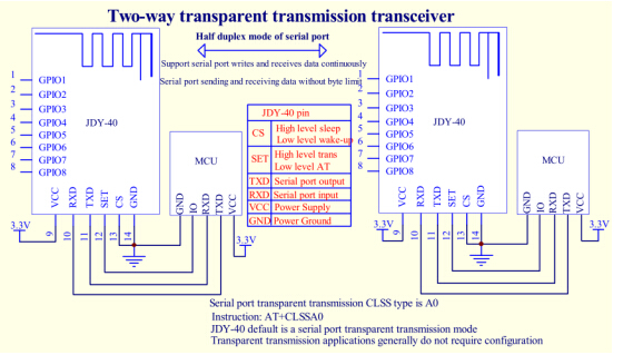 To access the GPIO between the two models you can setup the mode in four different mode
6>. CLSS type
| No. | Instruction | Response | Parameter |
| 1 | AT+CLSS<Param> | OK |
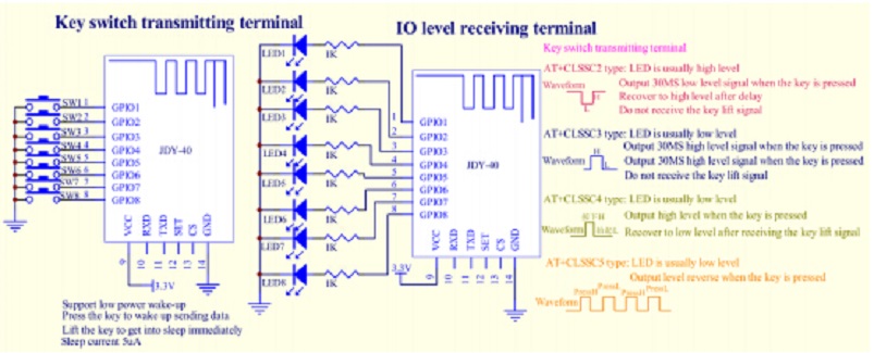
Param A0: Serial port transparent transmission(Transceiver) C0: Remote controller or IO key indicator light(Transmitting terminal) C1: remote controller or IO key without indicator light (Transmitting terminal) C2:IO is high level at normal level, low level after receiving signal and high level after delay 30mS C3:IO is low level at normal level, high level after receiving signal and low level after delay 30mS C4:IO is low level at normal level, receives pressed signal of high level and receives lift signal low level C5: The IO level is reversed when IO receives the pressed signal. Default Value:A0 |
| 2 | AT+CLSS | +CLSS=<Param> |